Wednesday, February 24, 2016

Beam Build

This write up is about building an I-beam. The assignment was to select a style of beam and build it. This page will cover the constraints, designing, and building of the I-beam. This is a document with the beam parameters. Here is the project:

There were three types of beams that we could choose from: an I-beam, H-beam, or a hollow box beam. There were also three parameters to the design: the weight, cost, and the deflection of the beam. The deflection and weight was easy. These could be found using the calculator from the previous page. The cost was different. How the cost was determined was be setting a cubic inch to $0.20 and each glue joint to $0.50. The cost could not exceed $9.00. The cost of the material was easy to determine as the volume was already in cubic inches. Now that the parameters are out of the way, designing was next. The design that was built is an I-beam.

The first thing to do was to see what type of wood was available. The store that the wood was purchased from was Hobby Lobby. Here is a picture of their wood rack:

Basswood and Bala Wood Selection


The main choices were basswood or balsa wood. The balsa wood was extremely light, felt like Styrofoam, and was far too flexible. The basswood was light, felt sturdy and had some flex, but not a whole lot. There was also cost to consider. The balsa wood costed more, but 20 - 50 cents extra. Once all of these parameters were considered, the final choice was clear: basswood. Once I decided what type the next choice was thickness. Here is a picture of Hobby Lobby's basswood selection:

Basswood Selection

These are the sheets of basswood. It comes in 3 or 4 inches wide by 24 inches long pieces. The outside dimensions of the beam needed to be 2 x 2 inches while weighing under 200 grams. The The wood also came in a variety of thicknesses, mainly 1/8, 3/16, and 1/4 inches. The final choice was three sheets of 3/16 x 4 x 24 inch basswood. The two main choices were the 1/4 or 3/16 inch thick pieces. The wood needed to be sturdy, but cost effective. The 1/4 inch piece was $4.79 while the 3/16 inch piece was $3.79. With cost and sturdiness in mind, the 3/16 inch was chosen for this project. Three pieces of wood were bought in case of a miss-cut.

The next task was to design the beam. Once again, it need to be 24 inches long, and 2 inches square. The thickness of the wood was 3/16". There were two flanges and one web. The web need to be 2" minus the flanges, so the web height is 1-5/8".

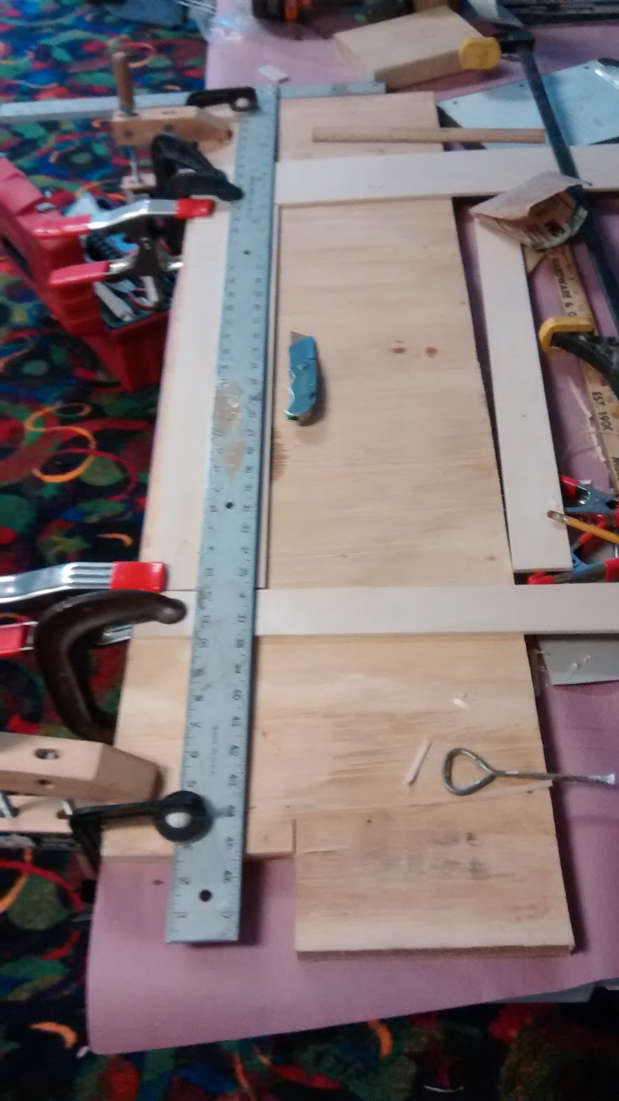
Now that the design was finalized, the biggest issue was how to cut the wood. A saw is a logical choice, but a saw has a kerf. A kerf is the amount of material removed by the saw when cutting. The boards were 4 inches wide and there was no spare material. The next option was a knife as it does not remove any material when cutting. Basswood is relatively soft and cuts readily with a knife. Here is my set up:

Setup for first cut

I was able to use a large framing square. It is made out of steel and has straight edges. There is heavy duty construction paper on top of the table and a piece of plywood on top of that. The center was marked, 2 inches, on the piece of basswood. The wood was then clamped to the plywood and the square was lined up with the center line. There are two spare pieces of wood the same thickness on either side of the wood. This gave more support to the square. The square was also clamped to the table. Once every thing was square and clamped down it was time to cut. The knife that was used was a basic utility knife with a disposable blade. It is sturdy and does not rattle or shake at all, as that would effect the cut.

The flanges were cut in several light passes while the blade was forced against the square. The blade did follow the grain of the wood and the cut was not perfectly straight or square. The edges came out slightly wavy and were then scraped and sanded smooth. The pieces came out to ≈ 1 15/16" because the blade followed the wood grain and had to be sanded and scraped smooth. However, these dimensions were close enough for this project. The same process was repeated for the web, but the piece was 1-5/8" wide. Here is another angle of the set up:

Side view of cut setup

The next step was gluing. The glue used was a Elmer's Wood Glue as this glue was on hand. The glue could have been a stronger variety, such as Gorilla Glue. However, standard wood glue is surprisingly strong. The wood itself will often break before the glue breaks or lets go. The center line was marked on the flanges, approximately 1 inch. Then a vertical center mark was made on both end of the flange. The lines were lined up and then the two boards were clamped together. This was a dry run for the glue up and lines were traced along the web. I then glued together one flange and the web. The apparatus used to spread the glue was an advanced one, my finger. This often works better than a tooth pick because you can better control pressure while spreading.

I then repeated the some process once the glue had cured, approximately eight hours. I did another dry run by clamping the second flange onto the plywood and then T-shaped piece was clamped on top. The outline of the web was then marked on the flange. The T-shape and the last flange were glued together as seen below:

Front view of final glue up

There were three different types of clamps used: 3 C-clamps, 2 small bar-type clamps, and one large spring clamp. The plywood did help, the bottom flange was clamped to the plywood so it would be steady and flat.

Here is a view of the beam from the side while being glued up:

End of beam

Here is the finished beam:

Side view
Top view

The beam is not much to look at because it is a simple I-beam.

The two hardest part about the build project was picking out what type of wood and then cutting it. If the project could be done over again, I would probably just use a table saw. It would make cleaner, straighter cuts and would be faster. There would have been two boards still used, but more waste. However, almost anyone can access a utility knife, clamps, and a straight piece of wood. I could have also used a stronger glue, but wood glue is readily available in a variety of stores and it was on hand.

Referring back to the parameters at the beginning of the page, the cost came out to $7.53. This was $1.47 under budget. There were two glue joints and the total volume was 32.625 in^3. To find the cost, the volume was multiplied by $0.20 per cubic inch. The cost of material came out to $6.525, rounded up to $6.53. The two glue joints added another $1.00, so $7.53.

To reiterate: this was another fun project, though tedious and time consuming. I did use only two of the three pieces of wood, so the actual cost was far under budget. As stated before, I should have used a table saw and maybe a stronger glue. Other than those two changes, I would not change anything, but we shall see how the testing goes.

Thursday, February 18, 2016

Final Project Ideas

Here are my three ideas for the final project:

1. Raspberry Pi Radio
    This is a small radio that made using the Raspberry Pi. It is fairly simple, but could be made more complicated. You could and a tuning knob to change the frequency for instance.

2. "Tweet-a-Pot"
    This is a Tweetable coffee pot. Say you are coming home from school or work and want coffee once you get there. It allows you to put the water and coffee into the pot and then start it remotely. That would be nice.

3. Secret Knock Door Lock
   I had seen this project a few years back, but I still think it is cool. It is a device that you suction cup onto the back of door. It is placed over the dead bolt and turns it when the correct pattern of knocks is achieved.


Wednesday, February 17, 2016

Beam Calculator

The project for week 5 was to make a calculator that would calculate the deflection of a beam. In this case the beam would be made of wood and would be one of three designs. The options were: an I beam, H beam, or a box beam.

Firstly, their are some terms that need to established. The basic terms to know for now are: flange, web, width, height, and thickness of material. Here is a simple diagram that I made using Inkscape. Inkscape was used to make all of the diagrams and formulas. This diagram points out all of the aforementioned terms:


The flanges are the top and bottom, while the web is the center support. The width and height are self explanatory, but the thickness of material is important. You need the thickness in order to use these formulas and calculations.

Now that those are defined, here is how I made the calculator:

I knew that in order to make a working calculator I would need formulas. A calculator needs formulas so that the values can be set to a variable. Then the variables are plugged into the formula and it spits out the answer. So the first thing I did was to get the formulas that Dr. Harris gave us. These were the Moment of Inertia and the Deflection formulas.

The formula for Moment of Inertia is this:


B = base or width of beam
H^3 = height of beam cubed
Multiple both together and then divide by twelve

This formula works for a solid beam, but what about and I beam? An I beam has two empty spaces on either side of the web. These spaces need to be removed from the formula as there is no support there. This can be done by finding that area and subtracting it from the whole area. The whole area is dubbed as positive space, or I-pos. The empty area is dubbed as negative space or I-neg. Here is a diagram to demonstrate positive versus negative space:


How we find I-neg is to remove the top and bottom, known as flanges, from the area. This can be done if we know the thickness of material. We take the thickness of material and multiply it by two and then subtract it from the height. We also need to get rid of the web. This can also be done if we know the thickness of material. Simply subtract the thickness from the base or width.

I then came up with a modified formula to find the negative area:


B = base
H = height
T = thickness

This formula allows you to take the base, height, and thickness of material and plug them in directly. (Base minus thickness) times (height minus 2 thickness) cubed and then divided by twelve. This gives you the actual area known as I-total. This is the Moment of Inertia. The result,  I-total, is used in the deflection formula. Here is the deflection formula:


P = concentrated load in Lbs
L = length, typically the span
E = Modulus of Elasticity
I = Inertia

(Load times span) cubed divided by (48 times Elasticity times Inertia)

Span is another term that needs clarification. The span of the beam is the distance between the two points of contact. Another way to think of span is the gap that the beam spans. The length is the overall length. This is used for calculating the weight. Here is a diagram showing length versus span:

I was able to use the deflection formula with any modification. However I did substitute the Modulus of Elasticity for the elasticity of basswood. The calculator is a one trick pony. It will only calculate the Moment of Inertia and Deflection for a basswood I-beam. The elasticity of basswood is 1,460,00 Lbs/in^2 or PSI. This means that  basswood will spring back until 1,460,00 pounds of force are applied. Basswood is fairly springy.

Once the formulas were squared away, the next step was programming. I decided not to start from scratch and use some existing code. I used some of my existing unit converter code plus some code that another person wrote. Dr. Harris recommended the class to look at the old classes and I came upon some usable code. The code was basic and in all honesty, pretty bad. Here is the student's page that wrote the code. The calculator had some odd formulas in it, the inputs were basic, and only one output.

I took my code, the aforementioned code, and a little bit of another code and made them into a working calculator. Here is her page for this calculator. I took the main layout of the rough code and stripped down to the bare codding. The only things I kept were the text boxes and the output coding. The main piece of coding that came from the second code was the text withing the text box. This is fairly simple, you create the basic text box code and then write in 'placeholder="namehere" '. Simply replace the namehere with whatever you want the text box to display.
placeholder="name"

Basic Beam Calculator


Width, height, thickness This is a calculator for a basswood I-beam.
This calculator has two fixed variables, the density and elasticity.
The maxium density of basswood is 37 Lbs per cubic Ft
The elasticity of basswood is 1,460,000 Lbf per square inch.

(in)
(in)
(in)
(in)
(in)

Length vs Span (Lbs)


(in^4)

(in)

(lbs) Here is my code in JSbin
Here is my code in a .txt format

The final design of the calculator is fairly straight forward. It is fixed for a basswood I-beam, as that is what I will be using. There are two fixed variables because it is made for basswood. These variables are the density and elasticity. This does make the calculator simpler for the average person as not many people would know the density or elasticity of basswood.

The major design change from the other calculators that I have seen is this: the diagrams are embedded into the HTML script. Once again, it clarifies which dimension is which and ensures that the correct values will be used. The code changes are fairly major, I as stated most of the existing code was stripped, removed, or trashed completely. The two biggest changes were the number of outputs and the formulas.

Overall, this project was time consuming and aggravating. The hardest part was getting the code to display the proper outputs. The overall time spent on this project was 10 - 12 hours. This calculator made me realize that there are a million different was to program the same thing. However, some ways are better than others. I did learn a lot, such as placeholder display, and it reinforced the idea that you do not need to start from scratch. Here is my code in a text highlighter:
<!DOCTYPE html>
<html>
<head>

  <script>
  function calculatefunction(){
    //Width = base. Set width to variable B:
  var B = document.getElementById("width").value; 
    //Set height to variable H:
  var H = document.getElementById("height").value;
    //Set thickness to variable T:
  var T = document.getElementById("thick").value;
    //Length = span. Set length to variable L:
  var L = document.getElementById("length").value;
    //Concentrared load = P. Set load to variable P:
  var CL = document.getElementById("load").value;
    //Set span to variable S
  var S = document.getElementById("span").value;
    
    //Find positive space (b*h^3)/12
  var Ipos = ((B) * (H*H*H)) / 12;
    //Find negative space, two negative spaces. ((Width - 1 thickness) * (h-2t)^3)/12
  var Ineg = ((B - T) * ((H - (2 * T)) * (H - (2 * T)) * (H - (2 * T)))) / 12;
    //Find Itotal:
  var Itotal = Ipos - Ineg;
    //Formula for Delta: ((P)(S^3))/(48(E)(I))
    //The average Modulus of Elasticity for basswood is 1,460,000 Lbf/in^2. I am simply substituting for E.
  var Delta = (CL * (S*S*S))/(48 * 1460000 * Itotal);
    //Output Delta as Deflection:
  var Deflection = document.getElementById("deflectionid");
   Deflection.value = Delta;
    //Out put Itotal as Inertia in in^4
  var inertiaAnswer = document.getElementById("inertiaAnswer");
   inertiaAnswer.value = Itotal;
    //Calculate density:
      //Density = mass/volume
      //Max density of basswood = 37 Lb/ft^3
      //37 Lb/ft^3 * 1ft^3/(12in)^3 = 0.02141 Lb/in^3
      //Density * volume = mass
  var volume = (Itotal * L);
  var mass = volume * .02141;
  var MoB = document.getElementById("MoB");
   MoB.value = mass;
  
  }
  </script>
</head>
<body>
  <h3> Basic Beam Calculator</h3>
  </br>
  <img src="https://blogger.googleusercontent.com/img/b/R29vZ2xl/AVvXsEhNU6wIzM2k8dTR-RQ99zGGznWntXppnraaCNTd4oq1bcXwOZcXHwKB48suqpFaVMyttrPXFYmTj7dKALVWUyQMyNm72sHca72rXN4XpkKTq1JzmKcVN-hAzencXhiKi-arBN-uqRF0FwY/s1600/I+beam+drawing.png" alt="Width, height, thickness" style="float:right;width:300px;height:200px;">
 This is a calculator for a basswood I-beam.
  </br>
This calculator has two fixed variables, the density and elasticity.
  </br>
The maxium density of basswood is 37 Lbs per cubic Ft
  </br>
The elasticity of basswood is 1,460,000 Lbf per square inch.
  </br>
  </br>
  <input type="number" placeholder="Width" name="width" id="width" /> (in)
  </br>

  <input type="number" placeholder="Height" name="height" id="height" /> (in)
  </br>
  <input type="number" placeholder="Length" name="length" id="length" /> (in)
  </br>
  <input type="number" placeholder="Span of Beam" name="span" id="span" /> (in)
  </br>
  
  <input type="number" placeholder="Thickness of Wood" name="thick" id="thick" /> (in)
  </br>
  </br>
<img src="https://blogger.googleusercontent.com/img/b/R29vZ2xl/AVvXsEiQGSFaPPB5eVd1U_QszohCfR-bjKswMOvbhGvmCJSZtzRRqEe7nT6pOOs4e_8fB3jEyVaM99EymL8EXMbZCQDURkx_lI_ZDS4Wc-CVoINO3G1auBvJJeGpSJYGerK_GOCpcx_QiF97uN8/s1600/I+beam+length+vs+span.png" alt="Length vs Span" style="float:right;width:300px;height:200px;">
  <input type="number" placeholder="Concentrated Load" name="load" id="load" /> (Lbs)
  </br>
  </br>
  <input type="submit" name="calculatebutton" id="calculatebutton" onclick="calculatefunction()" value="Calculate" />
  </br>
  </br> 
   <input type="number" placeHolder="Moment of Inertia" name="inertiaAnswer" id="inertiaAnswer" /> (in^4)
  </br>
  </br>
  <input type="number" name="Deflection" placeholder="Deflection" id= "deflectionid" readonly="true" /> (in)
  </br>
  </br>
  <input type= "number" name="MoB" placeholder="Mass of Beam" id= "MoB" readonly="true" /> (lbs)

  </body>
</html>

Friday, February 12, 2016

Cardboard Reindeer

This is about a side project. This was my original laser cutter project, but I decided to go with the more impressive project.

I Googled 'plywood reindeer plans' and I eventually found one that I liked.

The plans were far too big. I re-sized them to have an overall height of  ≈ 8.5 inches. I then had to go in and re-size the slots of the cardboard down to 1/8 or .125 inch wide. I also made two different sizes and one without antlers. I also modified the original plan to have a reindeer grazing and without antlers. I will go in depth about this project in a later post, so I will just skim over it now.

In order to cut them I needed to make the plans into a vector image. I did this by using Inkscape as I have mentioned in my previous articles. Here is the layout of the reindeer while still in Inkscape:

PDF file used for cut


Before I could even use the laser cutter I had to watch three videos and take a short test. The reason behind that is this: the laser is literally burning the material and cardboard is quite flammable. The laser cutter is potentially the most dangerous tool in the FabLab. There have been several instances of a project catching on fire while being cutout.

Once I completed the training for the laser cutter I could then use the cutter. The videos explains how to use the laser cutter, so I recommend you to watch the videos. Here are the reindeer still in the laser cutter right after it finished:

Still hot on the cutter

There are several different settings for the laser cutter. In this case the cutting parameters for the cut, such as speed and power, are listed on the front of our machine. It is a simple piece of paper listing different materials and thicknesses of said material. It then lists the power and speed settings to use. The settings were: 40% speed, 100% power, and 2500

I was able to get four reindeer out of a 20 X 10 inch piece of cardboard. I could have made the design more compact, but I thought that four reindeer was plenty. The slots are a tight press fit, but still come apart with some force. I wanted to be able to take them apart for storage, as I am 3 months too late for Christmas. I then assembled and arranged them:

A small herd of Reindeer

I thought that they turned out fairly well. Admittedly, they are more cute or neat than anything and not overly technical. There are a fun project that you could do with a child to get them interested in making stuff.

Here are the files for the reindeer:
PDF File
SVG File

Thursday, February 11, 2016

Laser Cutter

This project was made using the Epilog Laser in FabEd Charlotte. The assignment was to design a project and cut it using the laser cutter. The design had to fit within a 20 X 10 inch piece of cardboard. Here is my project:

I knew about this project for the previous 3 weeks and spent some time looking for ideas. I contemplated about making a cool and useful project, but I was stumped. I decided to look for some ideas. I tried a few different Google searches, such as laser cutter ideas and laser cutter projects. One of the first hits was Thingiverse. Thingiverse is a website that is made for people doing projects similar to this one. However, it is geared more towards 3D printing rather than laser cutters. Thingiverse is interesting because it shows you the projects and has downloadable files for the projects. I did look at some stuff there, but I did't see anything I liked.

I moved onto a different website, it is one that I had never thought of using this way. Pinterest. Pinterest is actually useful to get ideas. It allows you to save or 'Pin' an article or picture. You can make different albums or 'boards' to put these articles into. Pinterest was great for finding different ideas, but most of the neat things were essentially an add for that item. The link to the object or article was typically for a store and more often than not, Etsy. Etsy is an online store for makers or artists. If you have something to sell that is a small scale run or a single item, Etsy is a good place to try.

Dr. Harris also showed us some ideas from previous classes and pointed us towards the FabEd websites. I really liked a particular project. This project is an object called a dice tower. You put dice into the top and it rolls them for you. The dice then roll into a little tray that catches them.

Before I messed around with any software, I sketched out some full sized plans on paper. The overall size is supposed to be 8 x 8 inches.

The sketch on graph paper

I also did some calculations as to what would be the best angle for the slats. I did that using this set up:

Dice testing station
I took a piece of cardboard and stacked some different books until it reached 20 degrees. I tested the angle using several different types of dice. I used 20, 12, 8, 6, and 4 sided dice. I then picked a side to be face up.  I choose to use the '1' side for most of the dice. I did this to see how random the dice roles were. The results were good enough, though I would need to roll the dice into the top of the tower. I also used the same set up to test a 30 degree angle. I choose to angle the slats 20 degrees, this would role the dice sufficiently while still making the tower compact.

After I tested what the optimum angle would be, I started to design a dice tower in some modeling software called Creo. I am using this software for another class, DFT 170. This class is a engineering graphics class. I thought that Creo would be a good choice because I need to do some technical layout, such as angles. Creo is a little binding though, you need to know exactly what you are going to do before you start. Here is a screenshot of the incomplete design:

Incomplete Creo model

I decided to ditch Creo and try Inkscape, which worked fairly well. However, I quickly became over whelmed when I realized how hard it was. I needed to design the finger joints and size everything because I started from scratch. Designing a dice tower was too complicated and ambitious for my current skill set. I ran into another problem, it would not fit onto a 20 X 10 piece of cardboard. I reluctantly abandoned the idea of making a dice tower, but kept it in the back of my mind.

Anyway, I looked around Pinterest a came up with a few ideas and pinned them my 'board'. There are some neat projects, but I took a fancy to the idea of a lamp. I did find two cool examples. The first was a rocket ship shaped desk lamp. Sadly, this item was for sale and had no plans. I continued to looked around a bit more and found this lamp. This lamp is the same idea as the rocket ship one, but shorter, more compact, and shaped like a bomb. There were several different pictures, but once again it was an item for sale. Both of the articles lists the rough dimensions so I could guess the height. The two designs were too large for either design to fit on a single piece of cardboard, so I scrapped the idea.

I needed to find another project and by this time, it was two days before the project was due. I thought about what else I could do. Then I remembered the plywood reindeer that some people have in their yards around Christmas time. I designed and cut the reindeer and you can read about that project here. But here is a picture of them

A small herd of reindeer

After I finished designing and cutting the reindeer, someone else in my class used two sheets of cardboard. I then realized that I could use more than one piece of cardboard. It was a bit of a 'duh!' moment. I started again on making the dice tower. The main reason I ditched the idea was that it could not fit it onto a single piece of cardboard.

I went back to Inkscape and started again. I was rushed because the project was due in 1 1/2 days, not a whole lot of time. As I mentioned before, I tried to make the design from scratch, but I quickly became overwhelmed. I thought about it more and I realized that I could get a box design and then modify it, which is what I did. I went to a website that Dr. Harris recommended called MakerCase. MakerCase is quite handy, it allows you to input the size of the box and the thickness of material. You can also choose what size the finger joints are. It exports the designs to a PDF file for download.

I took the box designs and determined what would be the sides. I wanted the tower to be 8 inches tall and 4 inches wide. I used the largest finger joints I could which were .8 inch. I did this because it was easier to modify them later.

This is how the plans were modified. I took one of the side pieces and copied it. I then cut the bottom down to 1 inch thick and tacked it onto the left side of the box. That made the bottom 8 inches long. I then made a 1 inch square and rotated it 45 degrees and use the 'difference' option in Inkscape under the 'path' tab. I then took the same square and used it to make angle that joins the main tower to the tray.

I laid out the holes using this method:

I made a thin line using the rectangle tool and then angled to 20 degrees. The function I used was the 'transform' under the 'object' tab. The shortcut for it is shift+ctrl+M and then choose rotate in the menu. Being able to rotate an object a specific amount came in handy and I wished I had found it sooner. I then made a rectangle that was the length of the slat, 2.4 inches and .125 inches tall and rotated it to 20 degrees. I did the same for another rectangle that was .8 x .125 inches. The holes in the sides are .8 x .125 inches, a tight press fit. I made another two of those and placed them all onto the larger rectangle and the cut the middle one into the side. I copied and pasted the line along with the box set up to use again. The two extra boxes were for spacing.

I also had to make a 45 degree angle at the bottom. This layout was accomplished in a similar manner, but this slat was longer. I made extensive use of the measure tool in Inkscape. I made a .125 x 3.25 inch rectangle and rotated it to 45 degrees. I used the same line and spacing technique to layout this box. I then measured out the .8" slot and spaced it with two other rectangles. Here is the final product:

Final Side Layout

I then designed the bottom. I simply took the bottom piece, copied it, and removed the finger joints from one end. I then pasted in another bottom and modified the two to fit the bottom of the side. I only had to remove the finger joints from the different side piece and size it to eight inches. I decided to dub this piece as 'back'. The front panel was made by taking the back and cutting of the bottom two inches. This made the over all length six inches.

So far I had made the sides, back, bottom, and front. The next challenge was making the slats. I measured the inside distance between the two sides. I decided to make the slats 1/8" smaller and the tabs to be 3/16". This ended up being just right. The tabs stick out just a hair width from the sides. I also rounded the corners of the tabs by modifying the lines. I simply increased the slat length to fit the 45 degree space. I did have to redo the tabs, but I simply cut and pasted those. I also had to make the front tab of the tray. I did this the same way as the 45 degree. The tab was replaced by the finger joint and the overall length was decreased.

Here are the final two sets of cuts laid out on a 10 x 20 inch document:

Cut 1

Cut 2
Before I could even use the laser cutter I had to watch three videos and take a short test. The reason behind that is this: the laser is literally burning the material and cardboard is quite flammable. The laser cutter is potentially the most dangerous tool in the FabLab. There have been several instances of a project catching on fire while being cutout.

Once I completed the training for the laser cutter I could then use it. The videos explains how to use the laser cutter, so I recommend you to watch the videos. There are several different settings for the laser cutter. The main ones are the cutting parameters for the cut, such as speed and power. These settings are listed on the front of our machine. It is a simple piece of paper listing different materials and thicknesses of said material. It then lists the power and speed settings to use. The settings for cardboard were: 40% speed, 100% power, and 2500 frequency.

I then cut out the plans and assembled the tower. I brought my dice set into school and tested it there. I had to tape the tower together because the plans do not account for the kerf of the laser. I used some basic masking tape as it would come apart easily. Here is a picture of Cut 1:

Cut 1
Note, I did switch around the layout slightly. I  rearranged them because the cardboard was not 10 X 20, it was around 9.5 X 19 or so. I had to shift the a couple of pieces to make it fit. The actual layout is more efficient. I did not take a picture of Cut 2 because it was four pieces and unexciting.

Here are two views of the tower assembled:
Inside view of the back

Inside view of the front.
Here is a short video a two test roles:
The tower does handle large quantities of dice without any trouble.

One of the things that impressed me was how accurate the laser cutter is. The cuts were exactly the same as on the PDF file. I could design a piece to be this exact size and it cut it to that size plus/minus a hundredth of an inch. I did have trouble learning how to use the cutter. I had to take the test about ten times because some answers were multiple choice and technically right though incorrect for the test. I did make a mistake with the actual design. The finger joints are 1/8 of an inch. This width is fine for a press fit slot cardboard slot, but the cardboard is a little less than 3/16 of an inch. The edges of the card board were slightly recessed and did not look that great. I modified the designs to account for that flaw. The finger joints are now .187 of an inch wide, just under 3/16.

This issue stemmed from me only making one other thing with the laser cutter. The only joint was a press fit slot joint and I assumed that 1/8'' would work for a finger joint. I was wrong. There was another issue, this joints were slightly too loose. There is a couple hundredth gap between the top and bottom of the finger joint. I went into the design file and corrected these errors. I did not cut out the corrected design because I will make my next one out of 1/8" wood. I want this next tower to last. There will be quite a few changes to make for that design.

If I could redo this project from the beginning I would cut a simple box first. This would show me what limitations the material has, the actual thickness, and how well the material cuts. Another thing I would do is get an existing plan and modify it from the beginning. I did not need to reinvent the wheel. I tried to do that when I first started, I did not need to design finger joints. The sizing would also be right.

Overall, this was a fun project. It was tedious, but rewarding. Watching the laser cutter cut out the pieces is a really neat thing to watch. I am looking for to playing with this machine more this semester.

Here are the finished files for the project:
PDF Cut 1
PDF Cut 2
SVG Cut 1
SVG Cut 2

Wednesday, February 10, 2016

Extra Stickers

Here are some stickers that were made just for fun. Most of these are designs or images that I found online. The pictures were either .jpg or .png files that I put into Pixlr, it is an online photo editor and is handy for removing the background and cropping. I then ran the cropped and edited images through Inkscape. I used Inkscape to turn the raster image into a vector image and re-size them.

Here are the stickers:


This is the smaller Deathly Hollows sticker and was made using the re-sized .pdf file. These were cutout in black vinyl. The black vinyl is more visible than the silver vinyl.


PDF File
SVG File

This sticker is the next one I made. It is the logo for the Bethesda game, Skyrim. I found an image of it on Google and used my regular routine.

PDF file
SVG file

This is a sticker that I made for a friend. I did a search on Google for a D20 vector image and turned up this. It is an open domain image, so I can do want I like with it. I used Pixlr then Inkscape and saved it as a .pdf file. This one was tricky, the numbers were hard to peel out.


Friday, February 5, 2016

Manila Folder Portfolio

I foresaw a problem when I was going to cut out some stickers for my class project. I needed a way to carry the stickers around without loosing, bending, or pealing them. I decided that a simple manila folder would work, but the bottom is opened and the stickers would fall out.

Here is the manila folder:

 This is the folder when it could be opened


Here is the problem:
I then taped up the bottom with some OD green military surplus duct tape. This stuff is sturdy and inexpensive.
I used a pair of pliers to hold the tape down while I closed the folder. 
I then added another short piece of tape along the side. I finished it by adding more tape onto the outside to make it sturdier and look neater. I later cut the piece of tape on the side from 3 inches down 2 inches. This allowed better access to the contents while still holding them inside.


This is the finished folder. You can see on the bottom right corner where I trimmed the tape. I decided to put one of my stickers on the front of it. This sticker is from my second run, it is black instead of silver and the circle is actually a circle.

This project was quick. It only took 20 minutes, which includes me finding the folder at my house, taping, and then photographing it. Simple, cheap, easy, and effective.

Handy Software

Here are some useful websites, online tools, or software that I have found and have helped me:
  • JSbin
    • JSbin is a handy Java Script programming tool. It allows you to program in both html and Java Script. While you are programming it pops out your code in html format on the other half of the screen.
  • Tohtml
    • Tohtml is a basic script/code highlighter. You can select what type of code it is or let it auto-detect what type it is. You can also choose the color of background which also effects the color the highlights are.
  • Inkscape
    • Inkscape is basically a cheap version of Photoshop. Inkscape allows you to draw, crop, and edit pictures and images. You can also turn images into vector images, which what I found the most useful. I turned a fair number of images into vector outlines in order to cut them out. Inkscape does have some limitations, but it's free.