Friday, May 6, 2016

Smart Coffee Pot Build and Presentation

This is post is about designing and building a 'smart' coffee pot.

Assembled Smart Coffee Pot


This project was made to solve the problem of coffee after work or school. Often when one leaves work or school a cup of coffee is quite enjoyable. Instead of stopping at a coffee shop and spending $2 - $3 on a single cup, there could be a fresh pot of coffee waiting for you at home. A pot of coffee can cost 50 cents. This will save you a good deal of money and time after a few weeks of use. All that is required is to pre-load the coffee grounds and water into the pot as normal. Then turn of the power switch and walk away.

Here is how the Smart Coffee Pot was built and designed:

The first issue was the design. Our team met after the project was assigned and decided on a prototype design. The prototype would involve a relay, power cord, a standard wall outlet, and a coffee pot. We wanted the final design to be neat, simple, and user friendly. The coffee pot was the first component needed. We were not too picky at this point, we thought that another coffee pot would be used for the final model. The coffee pot was purchased used from Good Will for $5. The same one can be had from Amazon for $30 or $19 with Prime.

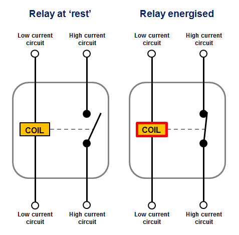
Once the coffee pot was purchased, the circuit could be designed. It had to supply power to the coffee pot. This was accomplished by using a power outlet. The power could be switched off or on by a relay or a manual switch. A relay is simply an electronically activated switch. It uses a electric coil to pull a piece of metal towards to close the circuit.


Photo Source: http://www.12voltplanet.co.uk/

A relay was included with the SparkFun inventor's kit that was purchased earlier in the semester. This relay is a SPDT relay while the diagram above shows a SPST relay. The major difference is that a SPDT relay has another terminal. This terminal is the default or 'preferred' one, the switch is resting on that terminal.

Wiring the relay was simple, a current needs to run through the bottom two leads. It needs at least 5v DC to activate. The data sheet for this particulate relay can be found here. This was done by soldering a pin cable to each terminal and then two gator clips were attached to a 9v battery. The AC power was wired to the top terminals. A multi meter was used to find the 'preferred' terminal and the AC power was wired to the other one. 

Here is a picture of the relay wired up:


Here is a video explaining the prototype circuit:


Once the prototype was finished, the final designing could commence. The components had to be chosen. The two parts that still had to be purchased were the WiFi module and the DC power supply. Both of these were bought off of Amazon. The power supply was $5 and the WiFi chip was $6. However, a second module was purchased because the first one did not work. The power supply was removed from the casing to reduce bulk. The 'power on' LED was re-soldered with longer leads and male headers. Female headers were soldered to the board. This reason will be apparent later. Here is the power supply:

Power supply board in the housing. Female headers on the left.

Once all of the components were in, a water resistant housing had to be designed. The housing would be mounted to the coffee pot and hold the arduino and other components. The housing was a crucial because the coffee pot would be in a kitchen. There was a chance that water could be splashed onto the circuit and cause a short cirucit. The design was started be placing the arduino board and the power supply board onto a piece of graph paper. The coffee pot was five inches wide, so the housing had to match that width. Conveniantly, the arduin and power supply board took up five inches with an ≈3/8 inch gap in between.

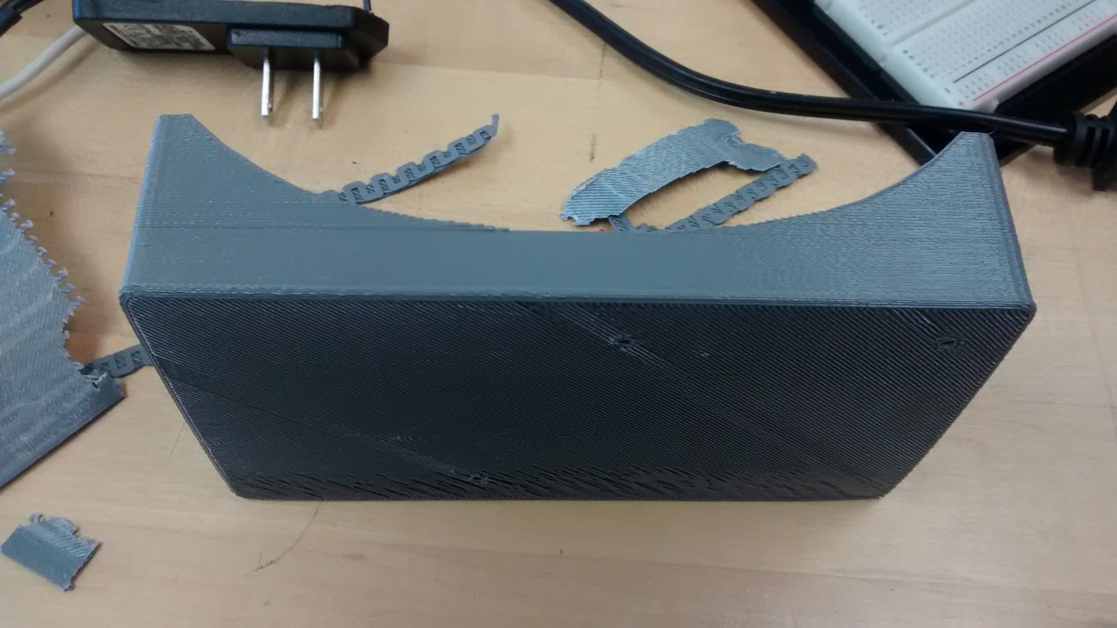
The coffee pot does have a slight curvature, so the bracket to hold the housing onto the coffee pot had to match that curve. This was accomplished by tracing the back of the coffee pot and measuring the distance between the center line and curve. As it turned out, this was fairly accurate. Once the dimensions were in hand, the housing could be designed in 3D. The software used to design the housing was Creo, which has been discussed on this blog before. 1/4 inch walls were used, which added 1/2 inch to the width . The final dimensions of the box are as follows:

  • Inside dimensions:
    • Width: 5" 
    • Depth: 2.75" 
    • Height: 1.5
  • Outside dimensions:
    • Add 1/2" to width and depth
    Printed box

The bracket was designed as a separate piece. The curve was plotted with points and then connected by lines. Then 1/4" was added to either side. The overall length was 5.5" while the depth was 1.375". This sketch was then extruded to be 5.5" tall. All of the outside corners have a 1/8' round. Here is he printed bracket:

Printed Bracket

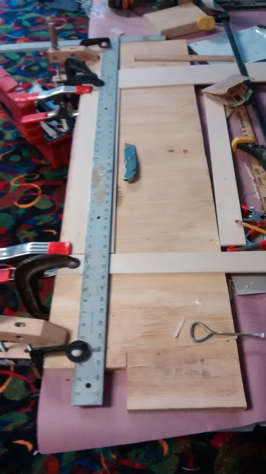
The lid for the box was designed in Inkscape and cut in acrylic using the laser cutter. Five holes were cut into the lid, one for the switch, two for the LEDs, and two for the screws for it to be mounted. Several test pieces were cut with cardboard as the supply of acrylic was running low. Here is the final lid mounted onto the box:

Acrylic box lid. The mounting brackets can be seen.

The next challenge was connecting the parts. I decided to use screws so that it could be disassembled if needed. Three tabs were modeled onto the box with 1/8" holes. Three matching holes were made on the flat side of the bracket. There were two self tapping screws included with the Inventor's kit. The holes were sized for these. The parts were assembled in Creo with the assembly tool. This ensured proper alignment of the holes. The screws that were actually used are #4 x 1/2" sheet metal screws purchased from Lowe's. 

#4 x 1/2" sheet metal screws, x5


Here is the packaging:

#4 x 1/2" sheet metal screws. Five per pack
The screws were $1.30 for five, which was all I needed. The box was then screwed together.

Once the housing had been designed, the arduino had to be mounted. This was done by designing a board mount. An arduino is too pricey to simply glue down. Again, Inkscape was used to design the mount. The screw holes were laid out to match the mounting holes on the arduino board. Five larger holes were cut in an 'X' pattern for the glue to adhere to. The arduino was mounted to the board with the self-tapping screws included with the kit. The mount was then glued to the inside of the box.

Arduino mount mounted onto the bracket. Notice the mounting holes
Now that the housing was completed, the circuit had to be assembled. This was fairly simple and quite similar to the prototype. A relay was wired to a transistor and 5v DC. The circuit can be found in the SIK guide on page 71 or 69. The LED part was discarded in favor of the LED being it's own circuit. It was also were AC power had to be connected. A diode was also added to prevent a EMF back flow. Here is the circuit on a breadboard:

IMG_20160503_144919591_HDR.jpg
Circuit laid out. The LED is on the left.

IMG_20160504_140542340_HDR.jpg
Relay wired up.

Now that the circuit was design, it had to be assembled. A circuit board could have been used, but I prefer to simply wire everything together. I work better with linear ideas and wiring everything together is more linear. The power for the LED and relay were wired together. Pin leads were wired to the transistor and LED. A servo also had to be included as a moving part.


Thursday, April 7, 2016

Arduino Input-Output project

This page will cover how to program an input/output for Arduino. This is a partial continuation of the previous Ardunio project, however, it will have an input as well. Here is the design and programming process:

Firstly, the arduino itself needs to be discussed. The most important step is to buy an arduino board. The actual board being used is the SparkFun RedBoard. It is a comparable board to the Arduino Uno, which is brand name equivalent. The RedBoard has the same features as the Uno for a lower price. I have not dealt with the Uno at all, but the RedBoard seems to be a good choice. The RedBoard also came in a kit that was required for this class. If a someone was looking into circuit prototyping, I would highly recommend this kit.

Now that choosing which arduino board to purchase is done the next step are the specifications. According to the arduino website, an Arduino Uno has 14 digital input/output pins and 6 analog input pins. The RedBoard has the same specifications as the Uno in virtually every way. The code is from the SIK guide provided by SparkFun with the Inventor's Kit. This project can be found on page 57. Here is the circuit working:


It is fairly simple, the circuit uses and RGB LED and a potentiometer. The potentiometer has different output values and those are sent to the arduino board. Based on what value is received the arduino then outputs different levels of voltage to the LED. An RGB LED has four leads, also known as legs. Three legs control what the color is while the fourth is the ground. This diagram shows which legs do what:

Photo Source: http://howtomechatronics.com/

There are also four resistors, x3 330 ohm and x1 10k ohm. These help prevent backload and lower and regulate voltage down to appropriate levels. This schematic can be found in the SIK guide, as aforementioned. I did change the soft/flexible potentiometer for a standard one, a dial potentiometer. This allows for precise control of colors. If you are interested in exact details, either watch the video or read the online PDF. The link to the code can be found in the SIK Guide PDF on page 9.

This was a simple and straight forward project. There is little, if any, to change or improve. This style of project could be applied to various projects, like with a stepper motor or servo. It would you to precisely control the position of an arm or how far the motor rotates. The applications are truly endless. Another fun and simple project.

Thursday, March 24, 2016

EGR 150-06 Team Consensus

Here is the Team Consensus for my EGR 150-06 team. This is a basic concept of I think the final project should be.

These are the questions that Dr. Harris posed:

  1. What questions do you ask? (Think of IDEO)
  2. Where do you get the answers you seek?
    • internet
    • books
    • interview
  3. What are the engineering skills you have to be successful?
  4. What are the engineering skills you lack to be successful?
  5. What is the solution trying to accomplish?
  6. What are the criteria that will be judged? (think safety in the IDEO video)
  7. What other questions are there?

Dr. Harris references a company called IDEO, they are a design company that tries to innovate while creating unique designs and solutions. There are some intriguing videos about IDEO that are worth watching.

Here is my consensus:

EGR 150-06 Final Team Consensus
Project: “Tweetable Coffee Pot”
  • What is the main goal?
    • To create a Twitter activated coffee pot
  • What questions will your team ask? 
    • How will we interface the arduino with the internet?
    • What electrical components will we need?
    • What will the layout be?
    • How will the 3D printer, laser cutter, and vinyl cutter be incorporated into this project?
  • Where will your team get the answers it seeks?
    • The main source of information will be the internet. We will use websites like Instructables and use citations when needed.
    • This article will provide much of the needed information 
    • Magazines may also be used.
    • We will also talk to the TAs in the FabLab for advice.
  • What engineering skills does your team have to be successful?
    • Basic circuit layout and building
    • Basic 3D design and layout
    • Creativity
    • Time mangement
  • What engineering skills does your team lack to be successful?
    • Programing skills with Python and C++
    • Fabrication
  • What are the criteria that will be judged?
    • How was the 3D printed part, vinyl cut part, and laser cut part incorporated?
    • What was the moving part?
    • Team work
    • Presentation of the project
    • Performance of the final product
    • Incorporation of the Arduino board
  • What other questions are there?
    • How much money will be spent?
    • Where will the resources come from?


Arduino Output Project

This article will cover some basic arduino design, layout, and coding. The parameters for this project was to do a sample project that comes with the arduino kit. The sample project was a basic blinking LED circuit and then modify the code and/or the design. It is composed of five components, not including the bread board and arduino itself. Here is the project:

Several weeks ago Dr. Harris told the class to order an arduino kit from SparkFun, an online electronics supplier. The choices for kits were these: the SparkFun Inventor's Kit for $100 or the SparkFun Mini Inventor's kit for $50. As the name suggests, the mini kit was simply a smaller version for half of the price. However, the regular kit include 2.5 to 3 times as much stuff as the mini.

First I had to download the arduino software. It is simple to install and straight forward to use. Once the software was installed the correct type of board had to be selected. In this case it was an Arduino Uno, the SparkFun RedBoard is an equivalent board. The basic programming for the project was already done, it was an example called 'Blinking an LED'. This is in the example program files and can be easily found.

There was one hiccup with the software, the program could not be uploaded to the board. This was due to the drivers for the arduino board not being installed properly. The proper drivers had to be downloaded and installed. The drivers can be found (here).

Now that all of the software was working correctly and the program could be uploaded, the hardware was next. The example that the class was told to use includes a diagram of the board set up. Here is the diagram and the board.

Source: SparkFun PDF, page 22

The arduino kit included a small tray to hold both the bread board and the arduino itself. The arduino has numerous output and input pins. The bread board is interesting, it is simply a group of contacts that can hold onto a pin or a lead. This allows simple and quick prototyping of a circuit as it does not need to be soldered together. The board's rows are number top to bottom and the lettered from left to right. This gives a concise way to notate where each component should go. These are essentially coordinates, like a10 or f5  In this case pin #13 was used as the output. The output wire, a green wire was used, was plugged into hole e2. The LED was plugged into c2 - c3. The negative leg of an LED is the shorter one and that side of the LED has a flat ridged. A small 300 Ω resistor was also used. The board set up can be seen the videos below.

The power for the board can be an external power supply or supplied through the USB port. In this case, the power was supplied through the USB port. The positive and negative wires were plugged into the proper holes and the circuit was complete.

Once the set up was done the test code was then uploaded. Here is the test code working:


The code makes the arduino send a signal through pin 13. This signal is then relaid to the bread board through the green wire. The code emits a signal through pin 13 that makes the LED blink for one second intervals.

Once the basic code was working it could then be modified. I tried to determine what would be a good project or challenge to code. I decided to stick with the single LED, but make it blink a pattern. I wanted the pattern to actually mean something, so SOS was chosen. The Morse code for SOS is this: dot-dot-dot-dash-dash-dash-dot-dot-dot. This is fairly simple and code could actually be useful. There are numerous brands of flashlights that can flash SOS.

Here is the SOS flash:


The board set up is the same as before, but the code was changed. Here is a link to the code used. The code has been saved as a .txt file type which can be copied and pasted to the arduino software.

This project was not too hard. The programming for the unit converters and beam calculator prepared the class for this project. As is typical with this type of project, the hardest part was getting the interface software to work, arduino to computer. But once that was squared away, everything else went smoothly. Another interesting, but tedious, project. I am looking forward to programming further for an arduino.

Thursday, March 17, 2016

3D Print Project

This post is about designing and printing an object with a 3D printer. It will cover what software was used to design and print, along with the parameters of the project. This post will also cover the types of materials, mainly plastics, that were available to use.

The main constraints for this project was that it needed to be designed by the student and fit within 1.5 x 1.5 x .25 inch box. Dr. Harris suggested some 3D modeling software such as SoildWorks or Tinkercad. I choose to use another software called Creo. I am currently using Creo in my Engineering Graphics class, so I am already familiar with it. Here is the process:

The first step was to sketch the design. The design is the final dimensions, except for height. This sketch is not included, as the one below is a better example. Once the paper sketch was completed the design could then be put into Creo. The design needed to be finalized before starting in Creo. If you are going to use Creo, you need to know exactly what the design is. As mentioned in previous posts, Creo is a not meant for creativity. Here is the first Creo sketch:

Sketch 1. This does show the dimensions.

The design was fairly simple. First a 1.5 x 1.5 inch square was sketched out in Creo. The design consists of a backwards 'E', a 'P' and the a small 'S'. This stands for my initials, EPS, and is effectively my monogram. The main pieces are 1/4" wide which makes the two gaps 3/8 x 5/8 inch. The 'P' was also simple. A circle was made with a diameter of 3/4" and then two lines were made. These two lines were made tangent with the circle and then this shape was connected with the backwards 'E'. A concentric circle was made with the center point of the larger with a diameter 1/4" and the same process was repeated.

Once those steps were done, the 'S' was next. This was difficult because I did not know how to make a letter in Creo. As it turns out, there is a text option. Choosing the font for the 'S' took the most time, about 10 minutes.

The next step was to extrude the sketch. This was done with the extrude tool. The overall thickness needed to be 1/4", so the logo was extruded to 1/8". Here is the extruded sketch:

Extrude 1, this was 1/8"

There needed to be a base in order for the 'S' to stay in place. This was done by making another sketch on the bottom face. This was also a 1.5 x 1.5 inch square.

Sketch 2, Creo can be hard to use, that is why it is sideways.

The sketch was then extruded 1/8" making the final piece 1/4" thick.

Extrude 2

There are a few limitations with a 3D printer, such as sharp corners. 3D printers handle smooth or rounded corners better than sharp ones. The four outside corners were smoothed with the round tool, the radius was set to 1/8". It was a simple matter of clicking on the corners to rounded. The model took an hour to complete, a small part of a free evening. Here is the final model:

Final model

Once the model was completed it needed to be saved to the correct file type. The default file type for Creo is a '.PRT', but the 3D printer software needs an different type such as a '.STL' or '.OBJ'. This was done by selecting 'save as' and then choosing the file type. The file type used was '.STL'. This was tricky, the part does need to be selected and then saved. A .STL file basically saves the model as polygons and simple shapes.

The printers in the FabLab are on a server. One of the laptops in the FabLab had to be used in order to access the server. Once this was accomplished, the printer could then be selected.

The printer that was used is a Printrbot Simple. This printer seemed to give good results and was simple to use. The Printrbot takes a code called 'G-code'. G-code gives the printer points or concordats to follow. It is accomplishes this by slicing the model into .8 millimeter slices or layers. In order to turn a .STL or .OBJ file into G-code, a third-party program had to be used. One of the TA's recommended a software called Cura. Cura is convenient because the model of printer is selected and then the file is loaded into Cura. The model is then positioned in Cura and then printed.

There were two different options for the printing material, known as filament. This filament is 1.5mm thick, comes in spools and a variety of colors. The two types of plastic available were ABS and PLA. ABS is the classic plastic, Lego bricks are ABS. PLA is a corn based product which will eventually degrade. For this process, Dr. Harris wanted the students to use PLA as these are first prints and in case of any mistakes. PLA can go into a landfill, but if ABS is used, your mistakes with literally last forever.

Here is the print in process with purple PLA filament:

Beginning of print
Approximately 1/3 done
Printing progress bar
Approximately 3/4 done
The overall print time was 45 minutes. The printer took 10 minutes to heat up and then 35 minutes to print. This printer gave fairly clean results. There were three other printers running at the same time and those were not printing nearly as cleanly. The results are decent, especially for a first print. Here is the finished piece:

Top-down view
Slanted view

There are still lines on the print, which could be sanded smooth. There is a trick with ABS to remove the lines on the piece. The piece is suspended over acetone bath in a sealed container. The acetone vapors react with the ABS plastic, acetone will dissolve ABS. The process does not take too long, maybe 45 minutes to an hour. However, this process can be sped up if the acetone is heated. This would create more vapor. It is recommended that you read this article as it goes into further detail. This article does talk about using an acetone bath which would accomplish the same effect.

Since this piece is simply a rough piece, more a proof of concept, it does not need to be finished. There was some basic clean up, a few thin strands of material from the print head. You will also notice that the curves are not smooth. This is due to the file type. The .STL saves the model as simple shapes, so the curves are made of triangles.

Overall, this project was quick and fun. This project took 2:15 - 2:30 to complete. The model took an hour or so to design it, another half hour to convert it and prep for printing. The overall print time was 45 minutes. The most tedious step was the print it self. It did feel like watching paint dry, unexciting.

There is really nothing that I would change, I might use ABS in a future print. I am happy with the print, and the color is not half bad either. This piece came out exactly 1.5 x 1.5 x .25 inches, which is one of the parameters. I will eventually mirror the design so that it can be used to make a sand mold and then casted in either copper or brass. This will  be used as a brand for branding various objects.

I do not wish to share these files, as they are of a private/personal nature and I do not want the them or the print to be recreated. If you do wish to obtain the files, drop me an Email.

Tuesday, March 1, 2016

Beam Testing

This write up is about testing the beam that was designed and built in the last three projects. This write up will show the expected results, actual results, and the reasons why the two did or did not match. The calculations will be both on paper calculations and from the beam calculator. Here are the results:

Firstly, the beam could not deflect more than 0.1 inch at a concentrated load of 250 lbs. The beam also had to be no more than 2 x 2 inches with a length of 24 inches.

The first step of testing the beam was to do some rough calculations. These are the ones from before I built the beam:

Rough calculations

This shows the on paper calculations and results. It also shows the results from the online calculator that was made previously. There is a fair bit of difference in between the two. The paper calculations gave that the inertia would be 0.821 in^4 and a deflection of .0253 inches. The calculator stated that the inertia would be .685 in^4 and a deflection of .0304 inches. The projected weight, according to the calculator, should approximately be 160 grams. The paper calculations are less accurate due to rounding in between steps. This should be the main source of error.

The beam was already built and needed to be tested. The beam had to be tested in the FabLab and one of the TAs was required to help or at least supervise. Firstly, the beam had to be weighed. There was an electronic scale at the FabLab. I brought the beam in on two separate days, a rainy day and a dry, sunny day. The first day the beam weighed 221.5 grams and the second day it weighed 175.5 grams. The change was astonishing, 40 grams of difference. This is due to how porous basswood is. It can readily absorb water. Now that the beam was weighed, testing the deflection was next. Here are two pictures of the beam in the testing apparatus:

Front view

Side view

The apparatus is simply an A-frame with roller supports and a downwards facing hydraulic jack, which and was operated with a socket wrench.. The jack provides a concentrated load, the same type as the calculations. There is also a dial gauge underneath the beam, it is visible in the first picture. The beam is placed in and the span was set. The rollers were already 18 inches apart, which is the correct span. The whole apparatus was clamped down to the table so that it could not move.

There is a small weight sensor between the jack and the beam. The sensor uses a USB connection with a computer to display how much force is applied to the beam. The sensor was ratted to 500 lb and if the beam was to be destroyed, the senor needed to be removed.

Onto the testing. The results were recorded by the TA who was helping to run the apparatus. Here are the results of the 2 x 2 by 3/16 thick basswood I-beam:

Weight of beam: 175.5 grams
Beam width: 1.97 inches
Beam height: 2.07 inches
Weight applied at 0.1 inch of deflection: 219 lbs
Deflection at 250 lbs: 0.12 inches
Pass or fail: failed

The beam did not pass all of the tests even though the calculations showed that it would. It was 0.07 inches too tall and deflected 0.02 inches too much. The calculations were incorrect. I believe that main source of error was the density of this bass wood. This basswood is rather thin, so any deviance in grain structure or pattern at all would cause major problems. I did try to pick the 'cleanest' wood, without blemish or knots, that could be found. However, the densities of materials are typically measured with large blocks of the material, not thin sheets. I should have realized this sooner and tested these specific pieces, but I did not.

The beam did pass the weight test, even though this was not an actual requirement. The beam was 24.5 grams under the implied weight restriction, which is pretty good. But it was still 15.5 grams over the projected weight. The 0.07 inches of extra height could have been corrected with light sanding on the tops of both flanges. However, the 0.07 inches was due to a slight gap while the glue cured and would not effect the deflection significantly. The beam was also 0.03 inches under the 2 inch restriction.

I am generally pleased with the results, though slightly disappointed that the beam failed the test. But it is still impressive that 3/16 inch basswood can support well over 250 lbs. If I could redo this project I would definitely test the density of the wood by finding the volume and weight. I would also test the deflection of the wood and see if it would pass. If I did go up to 1/4 inch wood I believe that the beam would pass the deflection test, but fail the weight restrictions. The aforementioned deflection calculations were significantly off, but the weight was also incorrect. This happened because the glue was not included with the calculations. An extra 10 - 15 grams should make up the difference of weight, so roughly 5 - 7.5 grams per glue joint.

Another fun project with some cool gadgets and calculations.

Wednesday, February 24, 2016

Beam Build

This write up is about building an I-beam. The assignment was to select a style of beam and build it. This page will cover the constraints, designing, and building of the I-beam. This is a document with the beam parameters. Here is the project:

There were three types of beams that we could choose from: an I-beam, H-beam, or a hollow box beam. There were also three parameters to the design: the weight, cost, and the deflection of the beam. The deflection and weight was easy. These could be found using the calculator from the previous page. The cost was different. How the cost was determined was be setting a cubic inch to $0.20 and each glue joint to $0.50. The cost could not exceed $9.00. The cost of the material was easy to determine as the volume was already in cubic inches. Now that the parameters are out of the way, designing was next. The design that was built is an I-beam.

The first thing to do was to see what type of wood was available. The store that the wood was purchased from was Hobby Lobby. Here is a picture of their wood rack:

Basswood and Bala Wood Selection


The main choices were basswood or balsa wood. The balsa wood was extremely light, felt like Styrofoam, and was far too flexible. The basswood was light, felt sturdy and had some flex, but not a whole lot. There was also cost to consider. The balsa wood costed more, but 20 - 50 cents extra. Once all of these parameters were considered, the final choice was clear: basswood. Once I decided what type the next choice was thickness. Here is a picture of Hobby Lobby's basswood selection:

Basswood Selection

These are the sheets of basswood. It comes in 3 or 4 inches wide by 24 inches long pieces. The outside dimensions of the beam needed to be 2 x 2 inches while weighing under 200 grams. The The wood also came in a variety of thicknesses, mainly 1/8, 3/16, and 1/4 inches. The final choice was three sheets of 3/16 x 4 x 24 inch basswood. The two main choices were the 1/4 or 3/16 inch thick pieces. The wood needed to be sturdy, but cost effective. The 1/4 inch piece was $4.79 while the 3/16 inch piece was $3.79. With cost and sturdiness in mind, the 3/16 inch was chosen for this project. Three pieces of wood were bought in case of a miss-cut.

The next task was to design the beam. Once again, it need to be 24 inches long, and 2 inches square. The thickness of the wood was 3/16". There were two flanges and one web. The web need to be 2" minus the flanges, so the web height is 1-5/8".

Now that the design was finalized, the biggest issue was how to cut the wood. A saw is a logical choice, but a saw has a kerf. A kerf is the amount of material removed by the saw when cutting. The boards were 4 inches wide and there was no spare material. The next option was a knife as it does not remove any material when cutting. Basswood is relatively soft and cuts readily with a knife. Here is my set up:

Setup for first cut

I was able to use a large framing square. It is made out of steel and has straight edges. There is heavy duty construction paper on top of the table and a piece of plywood on top of that. The center was marked, 2 inches, on the piece of basswood. The wood was then clamped to the plywood and the square was lined up with the center line. There are two spare pieces of wood the same thickness on either side of the wood. This gave more support to the square. The square was also clamped to the table. Once every thing was square and clamped down it was time to cut. The knife that was used was a basic utility knife with a disposable blade. It is sturdy and does not rattle or shake at all, as that would effect the cut.

The flanges were cut in several light passes while the blade was forced against the square. The blade did follow the grain of the wood and the cut was not perfectly straight or square. The edges came out slightly wavy and were then scraped and sanded smooth. The pieces came out to ≈ 1 15/16" because the blade followed the wood grain and had to be sanded and scraped smooth. However, these dimensions were close enough for this project. The same process was repeated for the web, but the piece was 1-5/8" wide. Here is another angle of the set up:

Side view of cut setup

The next step was gluing. The glue used was a Elmer's Wood Glue as this glue was on hand. The glue could have been a stronger variety, such as Gorilla Glue. However, standard wood glue is surprisingly strong. The wood itself will often break before the glue breaks or lets go. The center line was marked on the flanges, approximately 1 inch. Then a vertical center mark was made on both end of the flange. The lines were lined up and then the two boards were clamped together. This was a dry run for the glue up and lines were traced along the web. I then glued together one flange and the web. The apparatus used to spread the glue was an advanced one, my finger. This often works better than a tooth pick because you can better control pressure while spreading.

I then repeated the some process once the glue had cured, approximately eight hours. I did another dry run by clamping the second flange onto the plywood and then T-shaped piece was clamped on top. The outline of the web was then marked on the flange. The T-shape and the last flange were glued together as seen below:

Front view of final glue up

There were three different types of clamps used: 3 C-clamps, 2 small bar-type clamps, and one large spring clamp. The plywood did help, the bottom flange was clamped to the plywood so it would be steady and flat.

Here is a view of the beam from the side while being glued up:

End of beam

Here is the finished beam:

Side view
Top view

The beam is not much to look at because it is a simple I-beam.

The two hardest part about the build project was picking out what type of wood and then cutting it. If the project could be done over again, I would probably just use a table saw. It would make cleaner, straighter cuts and would be faster. There would have been two boards still used, but more waste. However, almost anyone can access a utility knife, clamps, and a straight piece of wood. I could have also used a stronger glue, but wood glue is readily available in a variety of stores and it was on hand.

Referring back to the parameters at the beginning of the page, the cost came out to $7.53. This was $1.47 under budget. There were two glue joints and the total volume was 32.625 in^3. To find the cost, the volume was multiplied by $0.20 per cubic inch. The cost of material came out to $6.525, rounded up to $6.53. The two glue joints added another $1.00, so $7.53.

To reiterate: this was another fun project, though tedious and time consuming. I did use only two of the three pieces of wood, so the actual cost was far under budget. As stated before, I should have used a table saw and maybe a stronger glue. Other than those two changes, I would not change anything, but we shall see how the testing goes.

Thursday, February 18, 2016

Final Project Ideas

Here are my three ideas for the final project:

1. Raspberry Pi Radio
    This is a small radio that made using the Raspberry Pi. It is fairly simple, but could be made more complicated. You could and a tuning knob to change the frequency for instance.

2. "Tweet-a-Pot"
    This is a Tweetable coffee pot. Say you are coming home from school or work and want coffee once you get there. It allows you to put the water and coffee into the pot and then start it remotely. That would be nice.

3. Secret Knock Door Lock
   I had seen this project a few years back, but I still think it is cool. It is a device that you suction cup onto the back of door. It is placed over the dead bolt and turns it when the correct pattern of knocks is achieved.


Wednesday, February 17, 2016

Beam Calculator

The project for week 5 was to make a calculator that would calculate the deflection of a beam. In this case the beam would be made of wood and would be one of three designs. The options were: an I beam, H beam, or a box beam.

Firstly, their are some terms that need to established. The basic terms to know for now are: flange, web, width, height, and thickness of material. Here is a simple diagram that I made using Inkscape. Inkscape was used to make all of the diagrams and formulas. This diagram points out all of the aforementioned terms:


The flanges are the top and bottom, while the web is the center support. The width and height are self explanatory, but the thickness of material is important. You need the thickness in order to use these formulas and calculations.

Now that those are defined, here is how I made the calculator:

I knew that in order to make a working calculator I would need formulas. A calculator needs formulas so that the values can be set to a variable. Then the variables are plugged into the formula and it spits out the answer. So the first thing I did was to get the formulas that Dr. Harris gave us. These were the Moment of Inertia and the Deflection formulas.

The formula for Moment of Inertia is this:


B = base or width of beam
H^3 = height of beam cubed
Multiple both together and then divide by twelve

This formula works for a solid beam, but what about and I beam? An I beam has two empty spaces on either side of the web. These spaces need to be removed from the formula as there is no support there. This can be done by finding that area and subtracting it from the whole area. The whole area is dubbed as positive space, or I-pos. The empty area is dubbed as negative space or I-neg. Here is a diagram to demonstrate positive versus negative space:


How we find I-neg is to remove the top and bottom, known as flanges, from the area. This can be done if we know the thickness of material. We take the thickness of material and multiply it by two and then subtract it from the height. We also need to get rid of the web. This can also be done if we know the thickness of material. Simply subtract the thickness from the base or width.

I then came up with a modified formula to find the negative area:


B = base
H = height
T = thickness

This formula allows you to take the base, height, and thickness of material and plug them in directly. (Base minus thickness) times (height minus 2 thickness) cubed and then divided by twelve. This gives you the actual area known as I-total. This is the Moment of Inertia. The result,  I-total, is used in the deflection formula. Here is the deflection formula:


P = concentrated load in Lbs
L = length, typically the span
E = Modulus of Elasticity
I = Inertia

(Load times span) cubed divided by (48 times Elasticity times Inertia)

Span is another term that needs clarification. The span of the beam is the distance between the two points of contact. Another way to think of span is the gap that the beam spans. The length is the overall length. This is used for calculating the weight. Here is a diagram showing length versus span:

I was able to use the deflection formula with any modification. However I did substitute the Modulus of Elasticity for the elasticity of basswood. The calculator is a one trick pony. It will only calculate the Moment of Inertia and Deflection for a basswood I-beam. The elasticity of basswood is 1,460,00 Lbs/in^2 or PSI. This means that  basswood will spring back until 1,460,00 pounds of force are applied. Basswood is fairly springy.

Once the formulas were squared away, the next step was programming. I decided not to start from scratch and use some existing code. I used some of my existing unit converter code plus some code that another person wrote. Dr. Harris recommended the class to look at the old classes and I came upon some usable code. The code was basic and in all honesty, pretty bad. Here is the student's page that wrote the code. The calculator had some odd formulas in it, the inputs were basic, and only one output.

I took my code, the aforementioned code, and a little bit of another code and made them into a working calculator. Here is her page for this calculator. I took the main layout of the rough code and stripped down to the bare codding. The only things I kept were the text boxes and the output coding. The main piece of coding that came from the second code was the text withing the text box. This is fairly simple, you create the basic text box code and then write in 'placeholder="namehere" '. Simply replace the namehere with whatever you want the text box to display.
placeholder="name"

Basic Beam Calculator


Width, height, thickness This is a calculator for a basswood I-beam.
This calculator has two fixed variables, the density and elasticity.
The maxium density of basswood is 37 Lbs per cubic Ft
The elasticity of basswood is 1,460,000 Lbf per square inch.

(in)
(in)
(in)
(in)
(in)

Length vs Span (Lbs)


(in^4)

(in)

(lbs) Here is my code in JSbin
Here is my code in a .txt format

The final design of the calculator is fairly straight forward. It is fixed for a basswood I-beam, as that is what I will be using. There are two fixed variables because it is made for basswood. These variables are the density and elasticity. This does make the calculator simpler for the average person as not many people would know the density or elasticity of basswood.

The major design change from the other calculators that I have seen is this: the diagrams are embedded into the HTML script. Once again, it clarifies which dimension is which and ensures that the correct values will be used. The code changes are fairly major, I as stated most of the existing code was stripped, removed, or trashed completely. The two biggest changes were the number of outputs and the formulas.

Overall, this project was time consuming and aggravating. The hardest part was getting the code to display the proper outputs. The overall time spent on this project was 10 - 12 hours. This calculator made me realize that there are a million different was to program the same thing. However, some ways are better than others. I did learn a lot, such as placeholder display, and it reinforced the idea that you do not need to start from scratch. Here is my code in a text highlighter:
<!DOCTYPE html>
<html>
<head>

  <script>
  function calculatefunction(){
    //Width = base. Set width to variable B:
  var B = document.getElementById("width").value; 
    //Set height to variable H:
  var H = document.getElementById("height").value;
    //Set thickness to variable T:
  var T = document.getElementById("thick").value;
    //Length = span. Set length to variable L:
  var L = document.getElementById("length").value;
    //Concentrared load = P. Set load to variable P:
  var CL = document.getElementById("load").value;
    //Set span to variable S
  var S = document.getElementById("span").value;
    
    //Find positive space (b*h^3)/12
  var Ipos = ((B) * (H*H*H)) / 12;
    //Find negative space, two negative spaces. ((Width - 1 thickness) * (h-2t)^3)/12
  var Ineg = ((B - T) * ((H - (2 * T)) * (H - (2 * T)) * (H - (2 * T)))) / 12;
    //Find Itotal:
  var Itotal = Ipos - Ineg;
    //Formula for Delta: ((P)(S^3))/(48(E)(I))
    //The average Modulus of Elasticity for basswood is 1,460,000 Lbf/in^2. I am simply substituting for E.
  var Delta = (CL * (S*S*S))/(48 * 1460000 * Itotal);
    //Output Delta as Deflection:
  var Deflection = document.getElementById("deflectionid");
   Deflection.value = Delta;
    //Out put Itotal as Inertia in in^4
  var inertiaAnswer = document.getElementById("inertiaAnswer");
   inertiaAnswer.value = Itotal;
    //Calculate density:
      //Density = mass/volume
      //Max density of basswood = 37 Lb/ft^3
      //37 Lb/ft^3 * 1ft^3/(12in)^3 = 0.02141 Lb/in^3
      //Density * volume = mass
  var volume = (Itotal * L);
  var mass = volume * .02141;
  var MoB = document.getElementById("MoB");
   MoB.value = mass;
  
  }
  </script>
</head>
<body>
  <h3> Basic Beam Calculator</h3>
  </br>
  <img src="https://blogger.googleusercontent.com/img/b/R29vZ2xl/AVvXsEhNU6wIzM2k8dTR-RQ99zGGznWntXppnraaCNTd4oq1bcXwOZcXHwKB48suqpFaVMyttrPXFYmTj7dKALVWUyQMyNm72sHca72rXN4XpkKTq1JzmKcVN-hAzencXhiKi-arBN-uqRF0FwY/s1600/I+beam+drawing.png" alt="Width, height, thickness" style="float:right;width:300px;height:200px;">
 This is a calculator for a basswood I-beam.
  </br>
This calculator has two fixed variables, the density and elasticity.
  </br>
The maxium density of basswood is 37 Lbs per cubic Ft
  </br>
The elasticity of basswood is 1,460,000 Lbf per square inch.
  </br>
  </br>
  <input type="number" placeholder="Width" name="width" id="width" /> (in)
  </br>

  <input type="number" placeholder="Height" name="height" id="height" /> (in)
  </br>
  <input type="number" placeholder="Length" name="length" id="length" /> (in)
  </br>
  <input type="number" placeholder="Span of Beam" name="span" id="span" /> (in)
  </br>
  
  <input type="number" placeholder="Thickness of Wood" name="thick" id="thick" /> (in)
  </br>
  </br>
<img src="https://blogger.googleusercontent.com/img/b/R29vZ2xl/AVvXsEiQGSFaPPB5eVd1U_QszohCfR-bjKswMOvbhGvmCJSZtzRRqEe7nT6pOOs4e_8fB3jEyVaM99EymL8EXMbZCQDURkx_lI_ZDS4Wc-CVoINO3G1auBvJJeGpSJYGerK_GOCpcx_QiF97uN8/s1600/I+beam+length+vs+span.png" alt="Length vs Span" style="float:right;width:300px;height:200px;">
  <input type="number" placeholder="Concentrated Load" name="load" id="load" /> (Lbs)
  </br>
  </br>
  <input type="submit" name="calculatebutton" id="calculatebutton" onclick="calculatefunction()" value="Calculate" />
  </br>
  </br> 
   <input type="number" placeHolder="Moment of Inertia" name="inertiaAnswer" id="inertiaAnswer" /> (in^4)
  </br>
  </br>
  <input type="number" name="Deflection" placeholder="Deflection" id= "deflectionid" readonly="true" /> (in)
  </br>
  </br>
  <input type= "number" name="MoB" placeholder="Mass of Beam" id= "MoB" readonly="true" /> (lbs)

  </body>
</html>